ONLINE REGISTRATION
Close

ONLINE REGISTRATION
Close
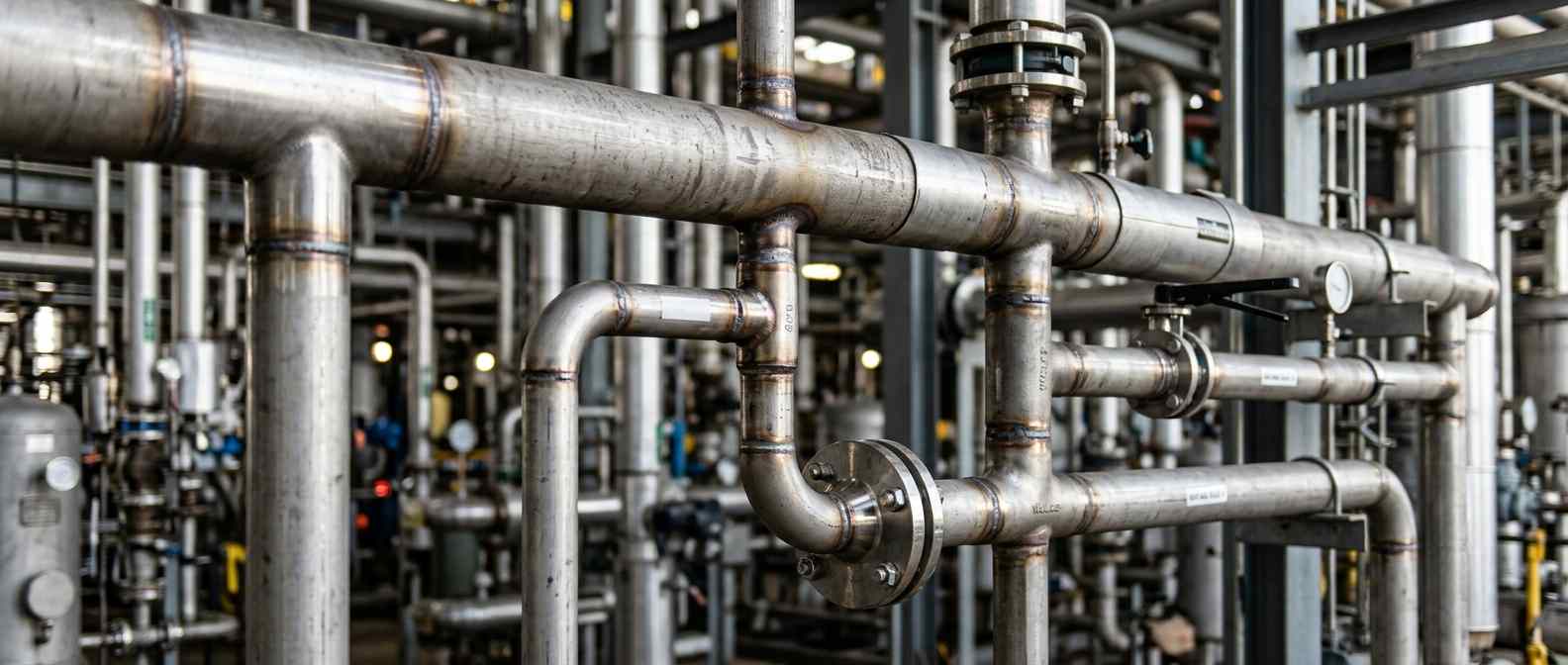
Proper pipe branching dictates system pressure and structural integrity. Every time you punch into a run pipe to divert flow you create a weak point. The solution requires matching your connection method directly to the fluid velocity and stress load using code calculations for forged fittings or standard tees.
A branch connection is any physical intersection where a secondary pipe diverts flow from a primary header pipe.
The main line acts as your header piping. Inside the facility, the line pulling away from it serves as the branch. Getting this intersection wrong causes severe turbulence.
But here is the thing. You cannot just cut a hole and stick a pipe in it.
Every cutout removes vital material. You have to replace that lost strength through careful reinforcement. If you ignore this basic principle of pipe branching the joint will inevitably rupture under stress.
There are several ways to execute pipe branching but three methods dominate commercial fabrication.
Standard tee fittings provide a prefabricated intersection for your piping systems. You buy them and weld them directly into the run pipe.
These components work perfectly for small diameter lines and low pressure applications.
They save time on the shop floor during assembly. Just remember they require three separate butt welds to install completely. That means more inspection points for your quality control team. A standard tee creates a harsh ninety degree turn that causes immediate pressure drops.
When planning your pipe branching weldolet installation stands as the heavy hitter for high pressure systems.
These forged fittings sit directly on the outside of the header. They provide their own heavy reinforcement right at the joint where stress concentrates the most.
And honestly they give you the cleanest flow characteristics available. A weldolet features a contoured internal profile. This smooth transition helps the fluid turn the corner with far less friction and wear.
Saddle connections and direct stub ins represent the rawest form of branch fabrication.
You profile cut the branch pipe to match the exact curvature of the header. Then you weld it straight onto the exterior.
Sometimes you must add a separate reinforcement pad around the joint. This takes serious skill. Your fitters will spend much more time grinding the metal to achieve a perfect gap. I see guys try to rush saddle connections all the time. They leave large gaps in the fitment and try to fill them with excess weld metal. That introduces stress risers into the joint.
Selecting the right approach comes down to basic math and project constraints.
A standard tee requires you to cut the main line completely in half. A weldolet only requires one single hole cut into the side of the pipe wall.
Cutting the entire pipe disrupts the structural continuity of the header. Drilling a single hole preserves much more original pipe strength.
Here is a breakdown to help you decide:
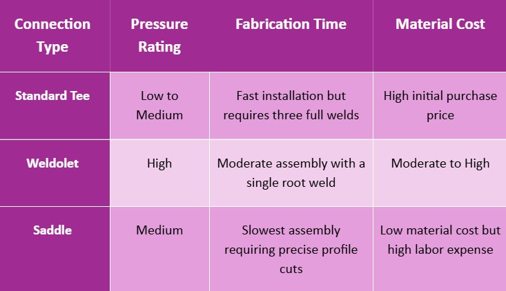
You save money on materials with a saddle but you pay for it in labor hours. A tee costs more upfront but requires far less fitting skill.
Executing field pipe branching requires tight control over your cuts and heat input. Successful pipe branching on a live system means strict adherence to safety protocols.
Here is how you handle tying into an active header.
You must constantly monitor your heat input during this process. Pouring too much heat into the header pipe causes it to warp. A warped header ruins the alignment for the rest of your piping run.
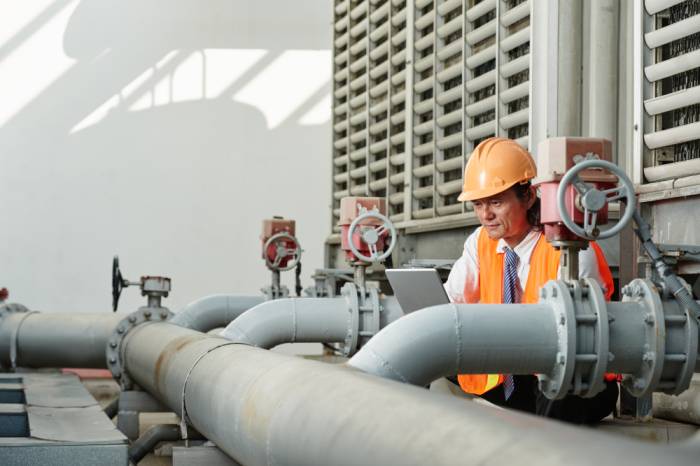
ASME B31.3 dictates the strict rules for proper pipe branching in process plants.
This code tells you exactly how much reinforcement your joint needs based on wall thickness and operating pressure. Many contractors assume the header wall is thick enough to handle the stress on its own.
Let me give you a common example. A fabricator cuts a massive hole for a lateral line but skips the area replacement calculation entirely. The system goes online and the internal pressure spikes rapidly. The joint cracks right at the toe of the weld.
Always run the area replacement calculation before you strike an arc. Your pipe branching strategy depends entirely on that simple math.
Flawless pipe branching protects your facility from catastrophic failures and expensive unexpected downtime.
But getting the math and the welds perfect takes deep industrial experience. You need a fabrication partner who understands the strict codes governing header piping and structural branch connections.
UC Design and Fabrication brings decades of heavy industrial experience to your next commercial project. Contact us today to build resilient piping systems that hold the line under pressure.
You must calculate the internal area removed from the header. Then you determine if the remaining metal provides enough strength to handle your specific system pressure.
Yes it does. Fluid hitting a sudden intersection creates intense turbulence and friction. This disruption causes a noticeable drop in the overall line pressure across your system.
This occurs when the intersecting pipe enters the main header at an angle other than ninety degrees. Piping engineers use this method to minimize fluid friction drastically.
You can achieve this using a hot tapping machine. This specialized equipment drills into the active header while maintaining pressure and preventing any fluid from escaping.
Fabricators typically lay a full penetration groove weld for the root pass. They follow this up with heavy fillet welds to secure the outer reinforcement pad.